14-Pin Cruise Control System
For Mercedes-Benz and Porsche
Servo/Actuator Diagnostics
Updated: 21 February 2019
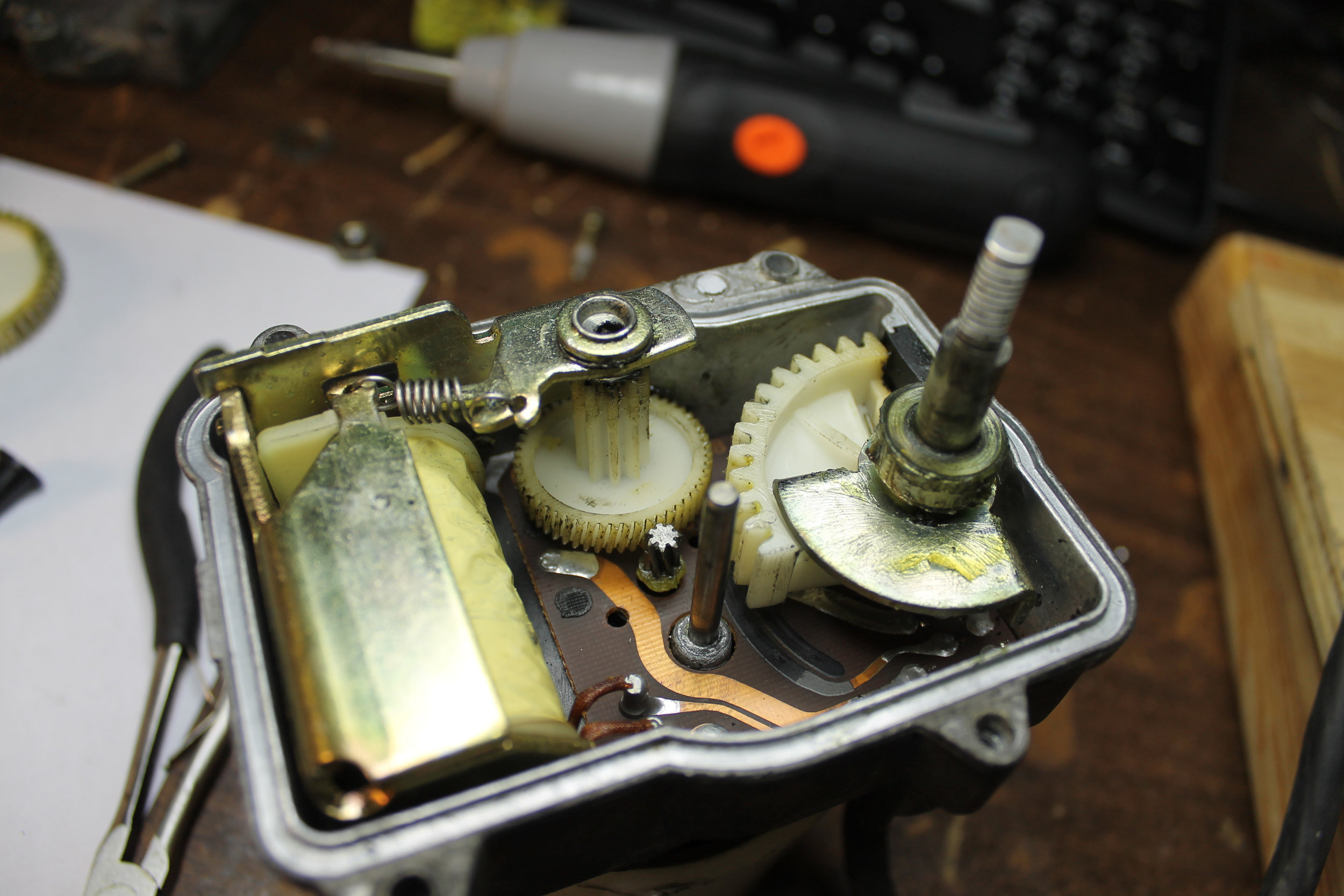
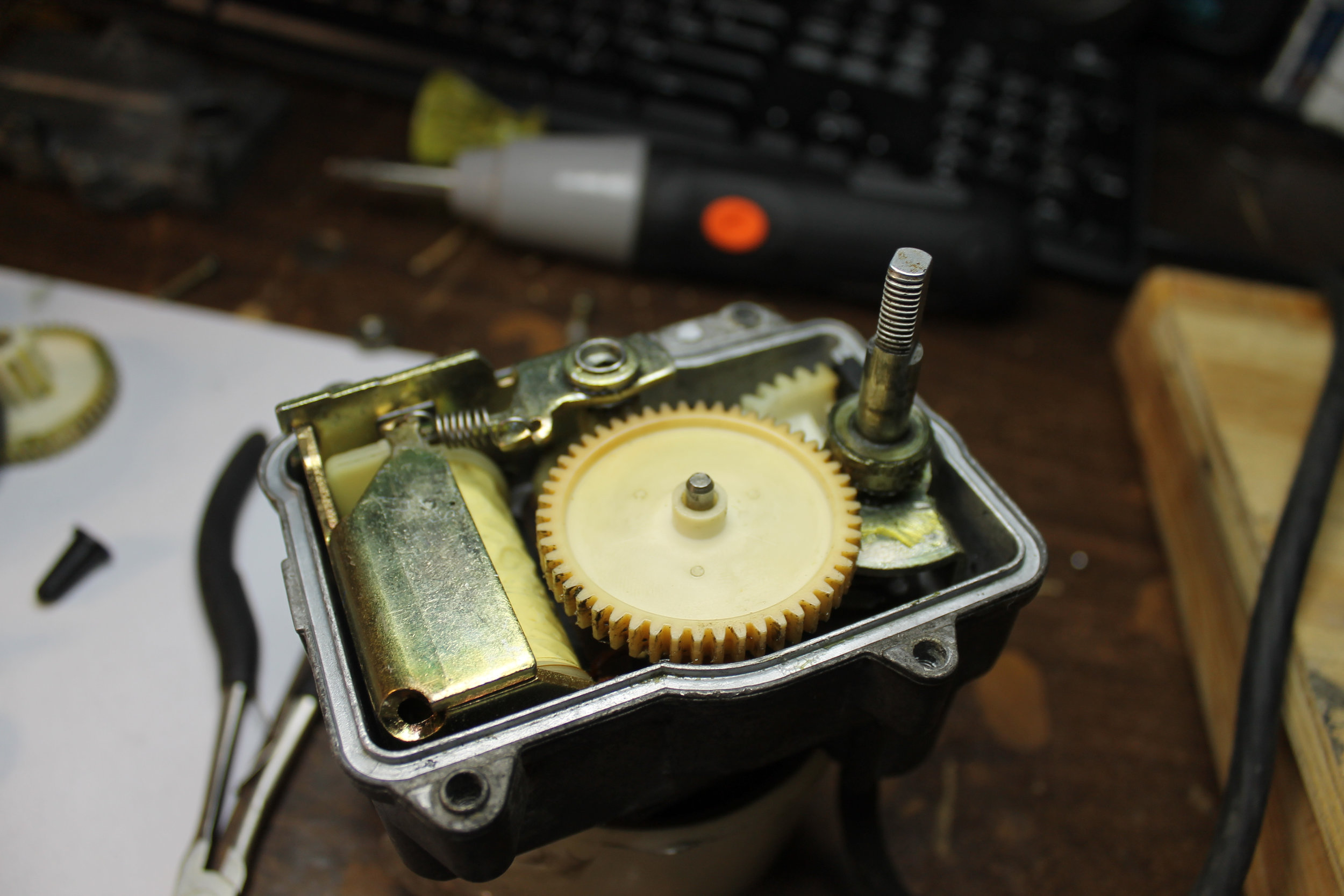
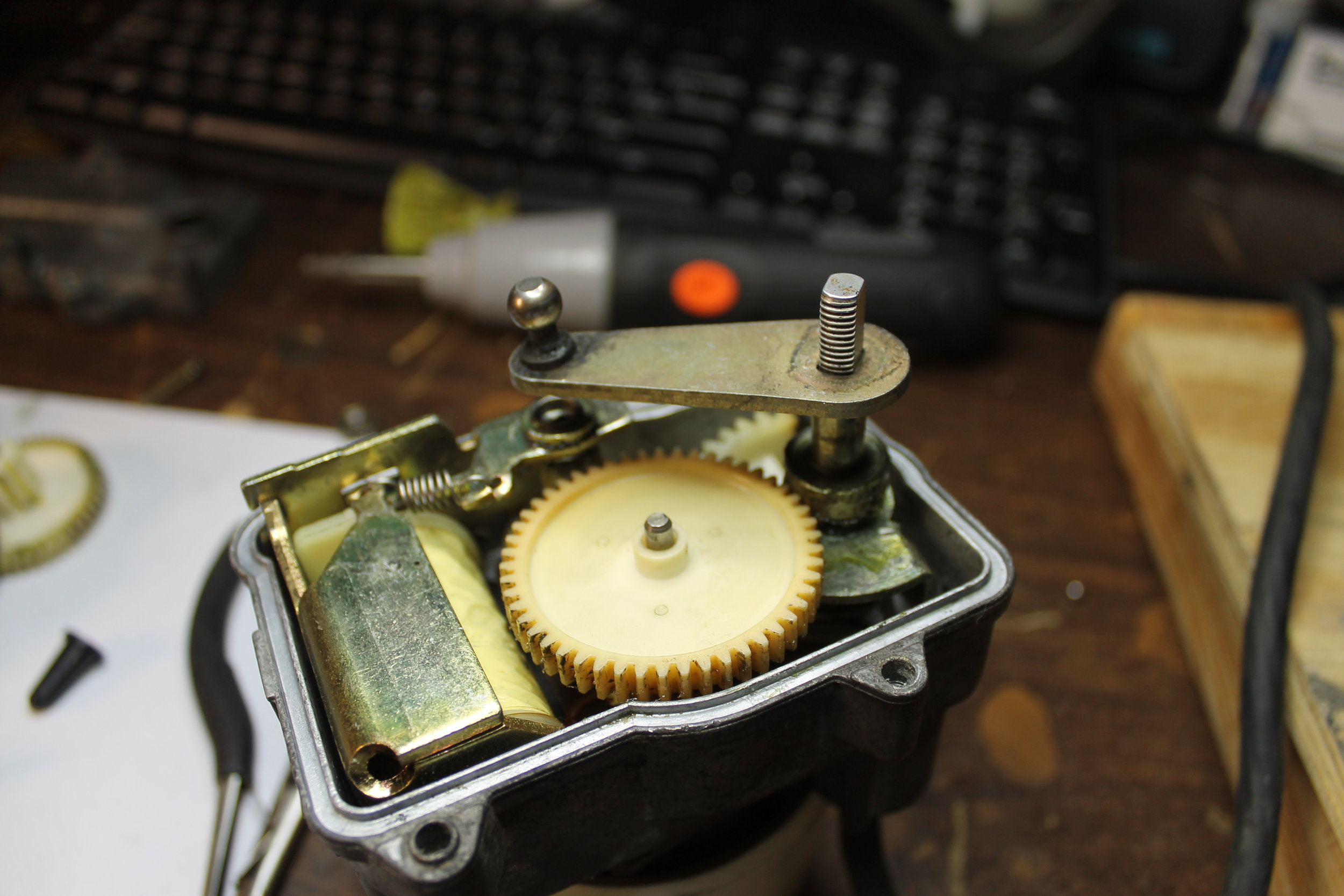
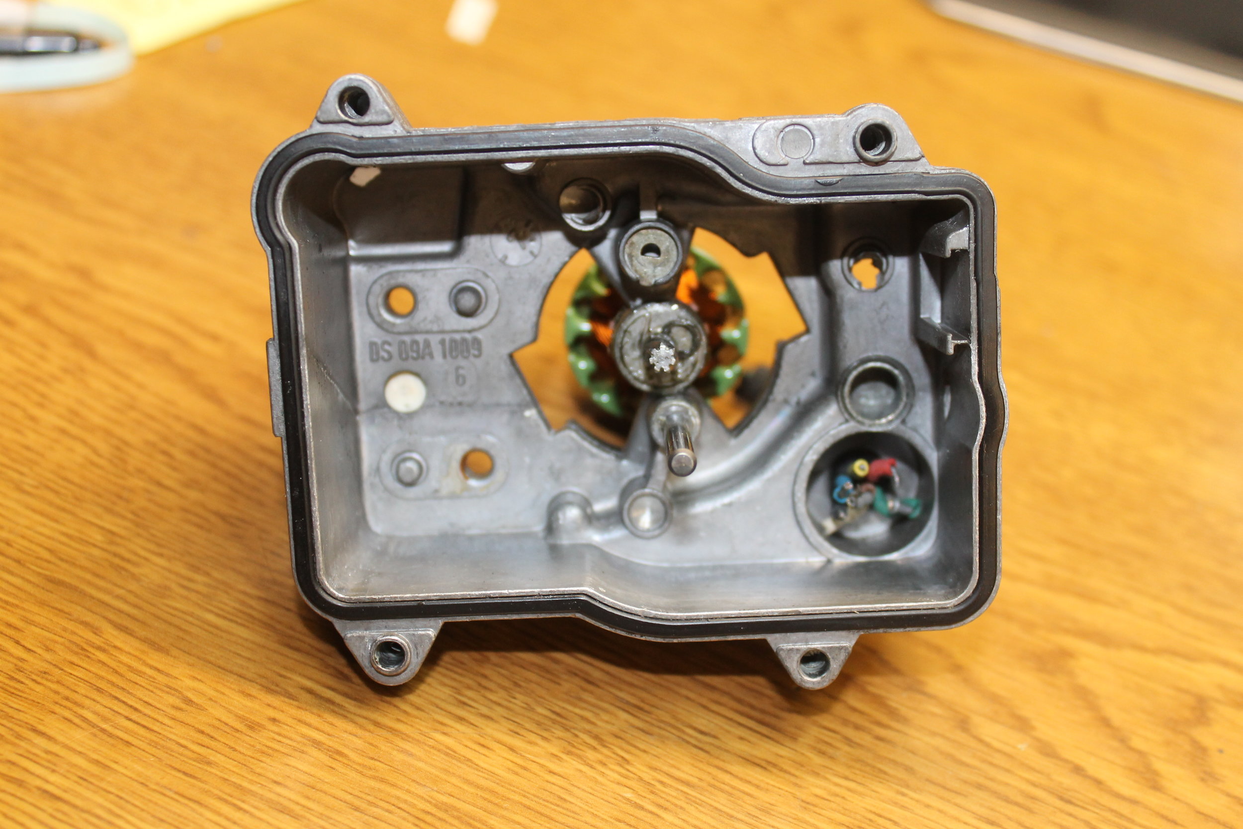
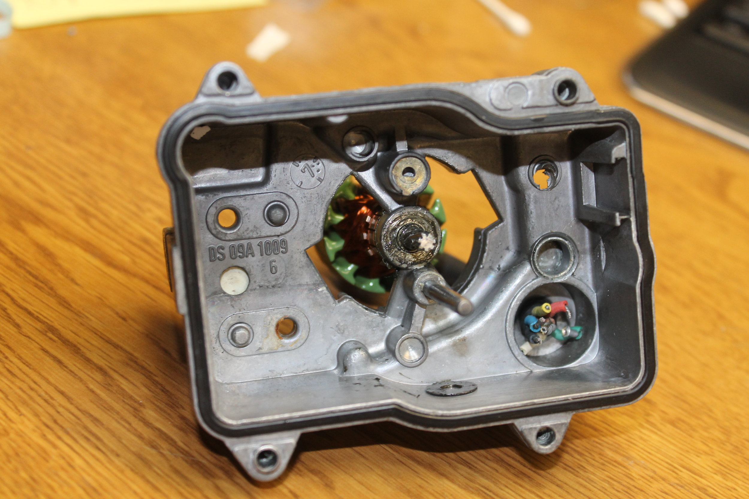
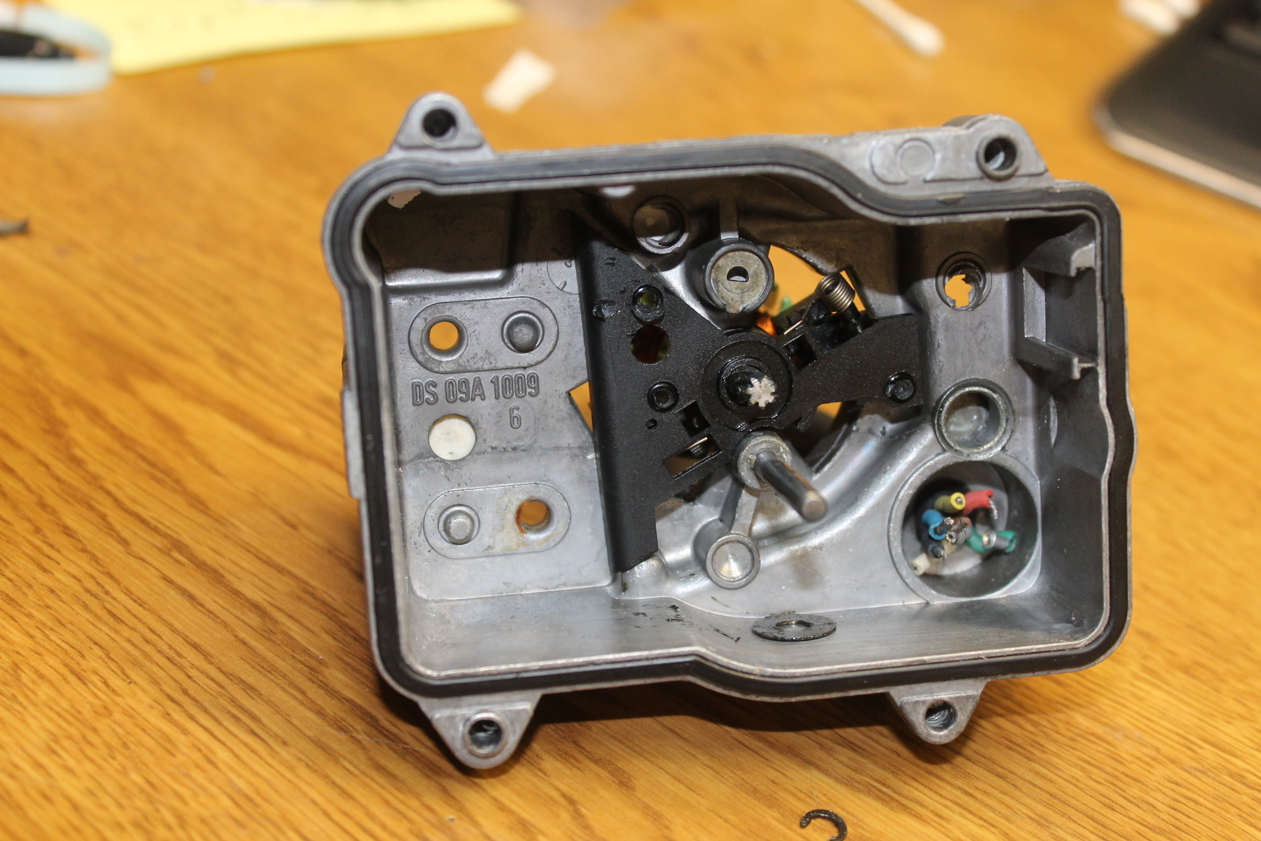
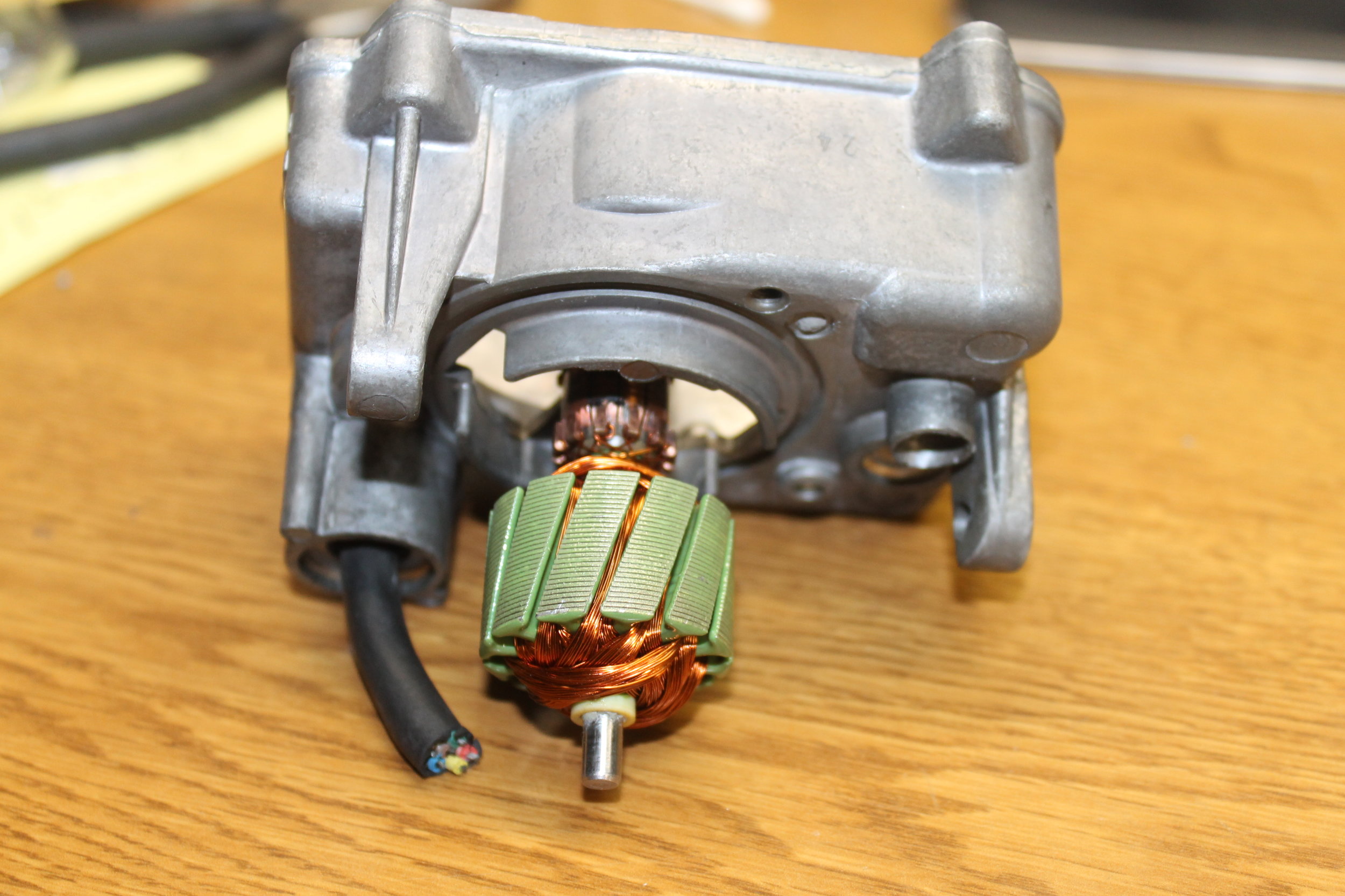
So, you're here to test out your actuator right? Wonder whats in it? How it works? Take a look at the end of this page for a photo album!
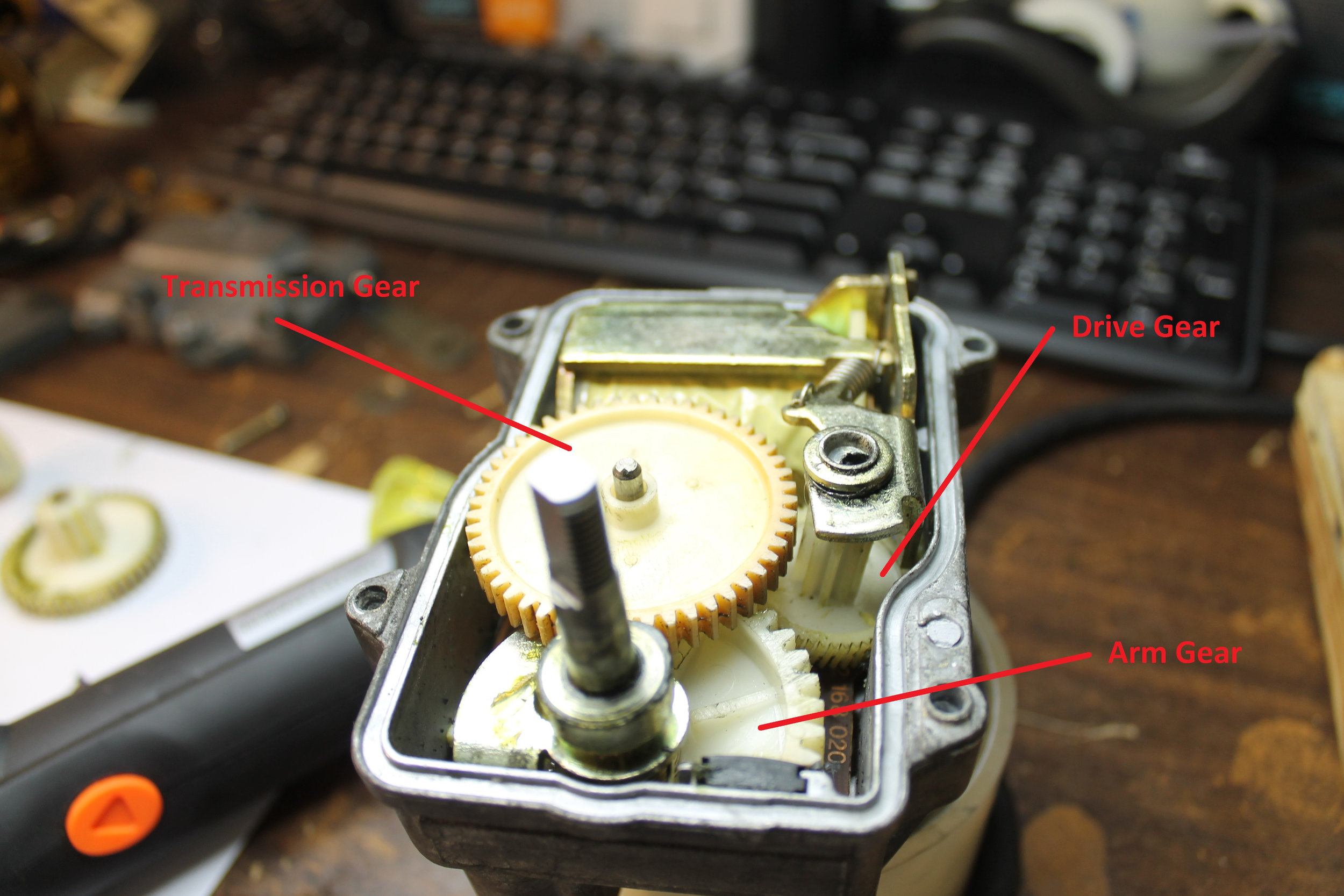
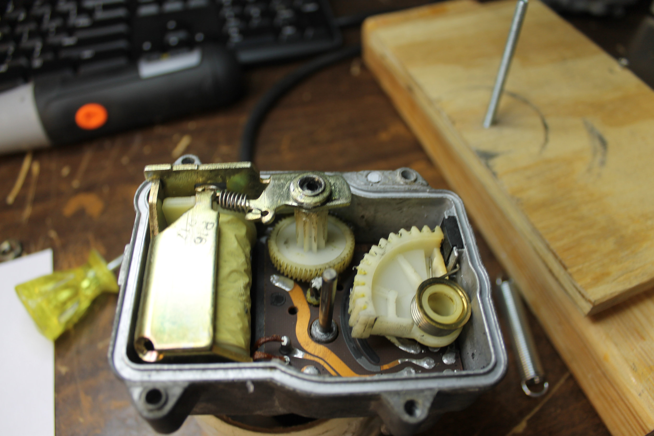
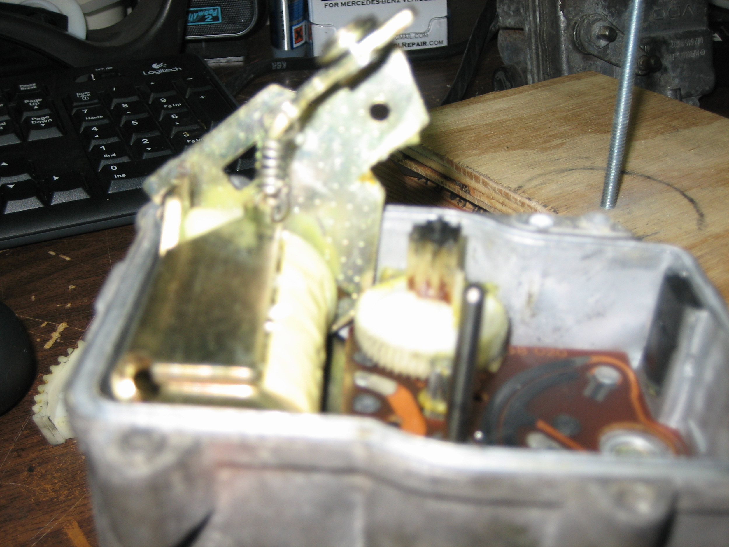
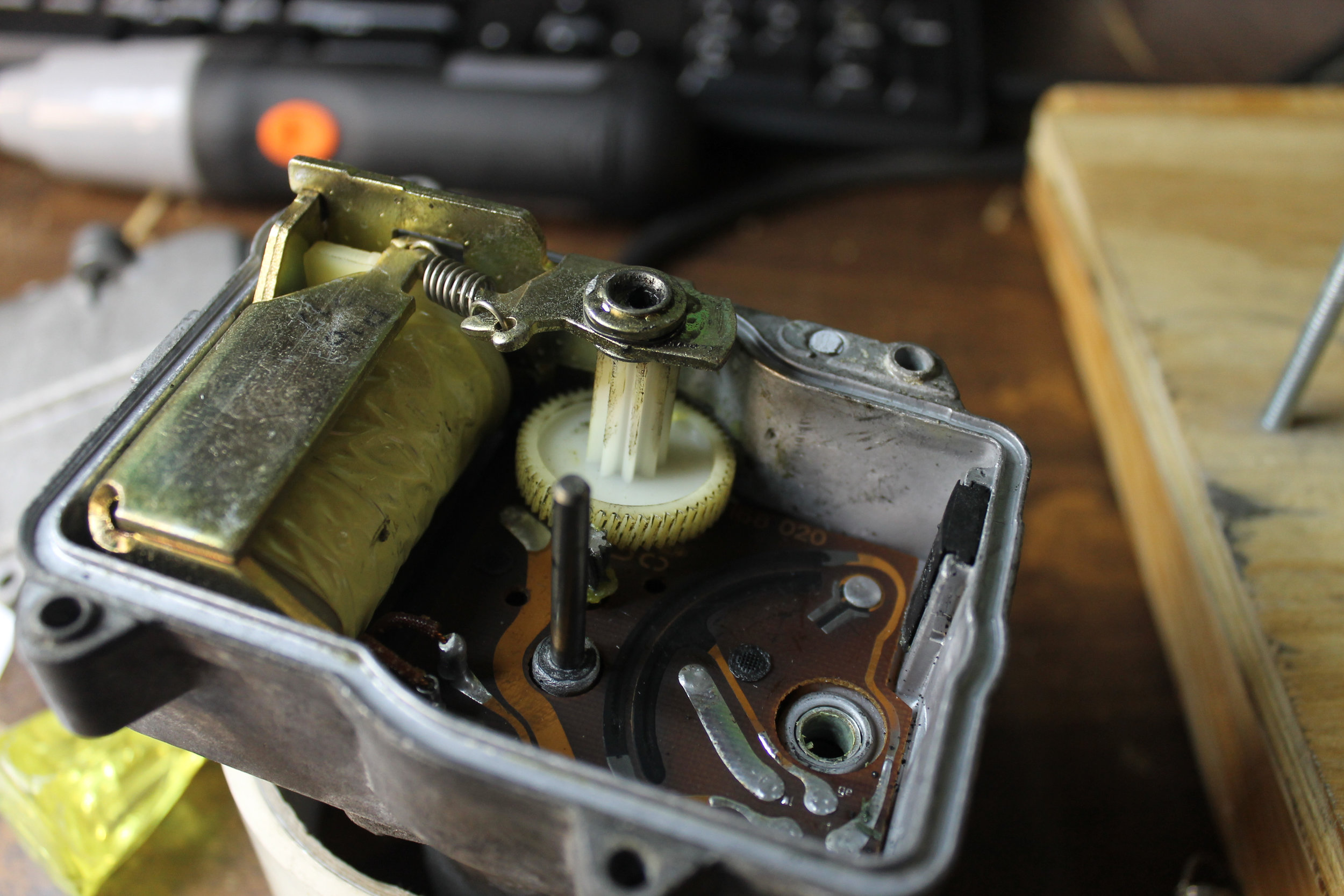
The cruise control actuator consists of the following items:
DC Motor
Solenoid
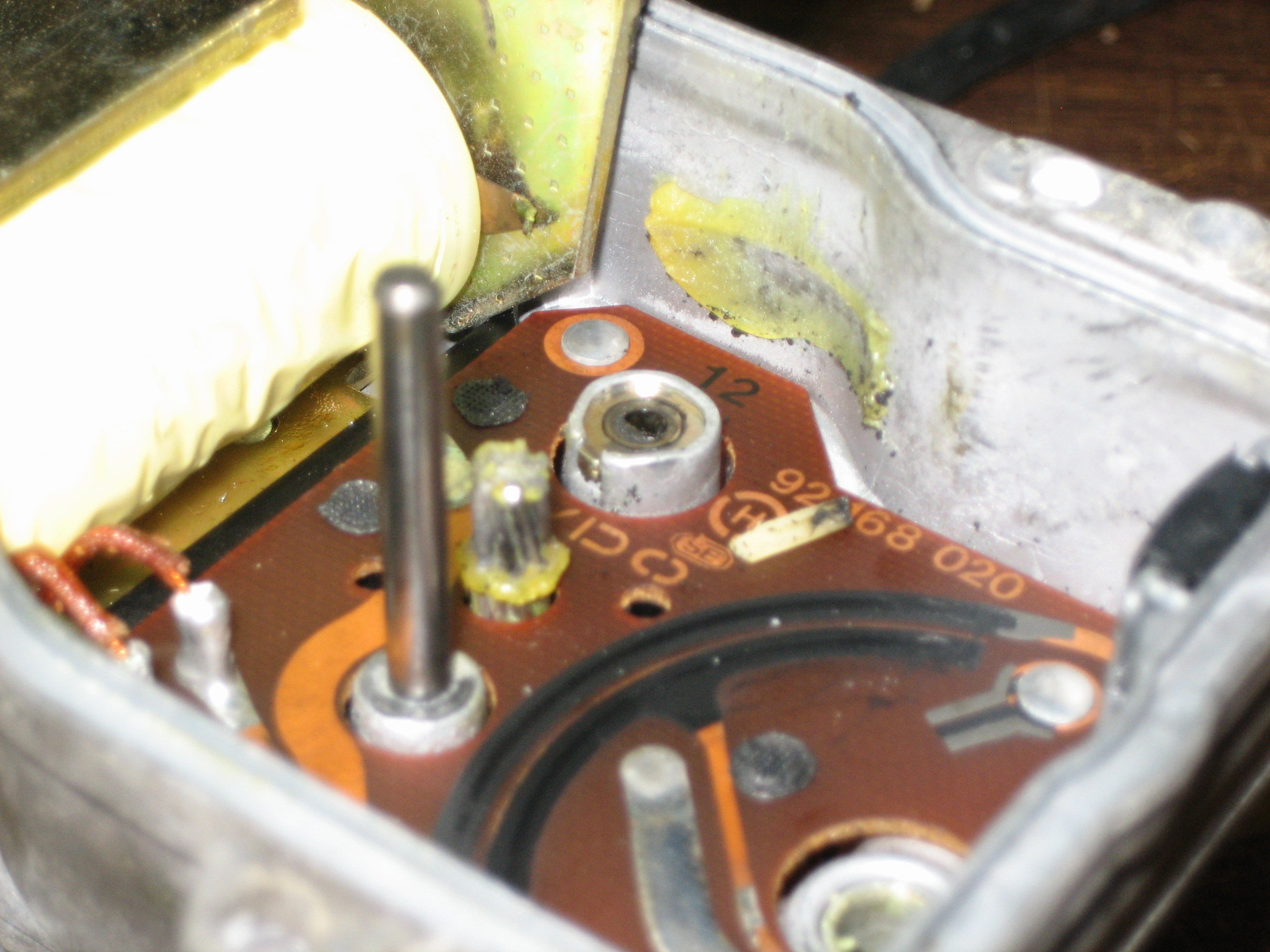
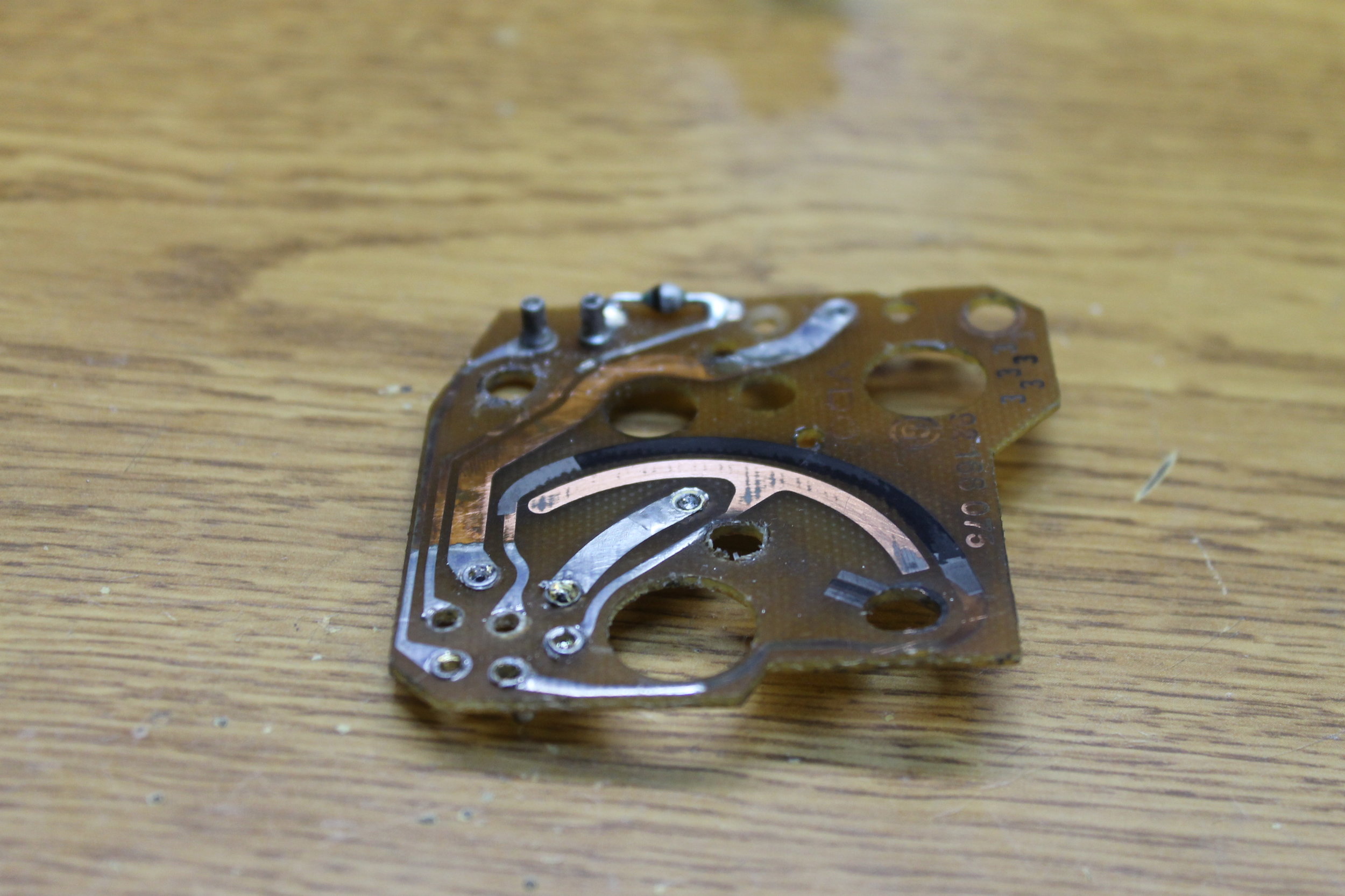
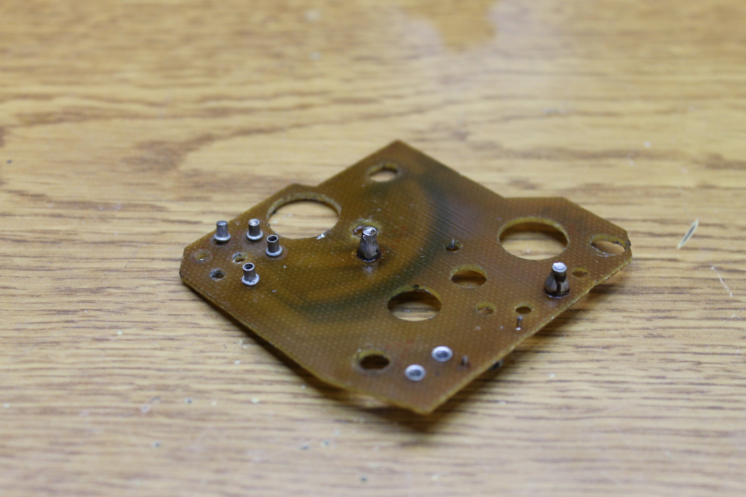
Position Feedback Potentiometer
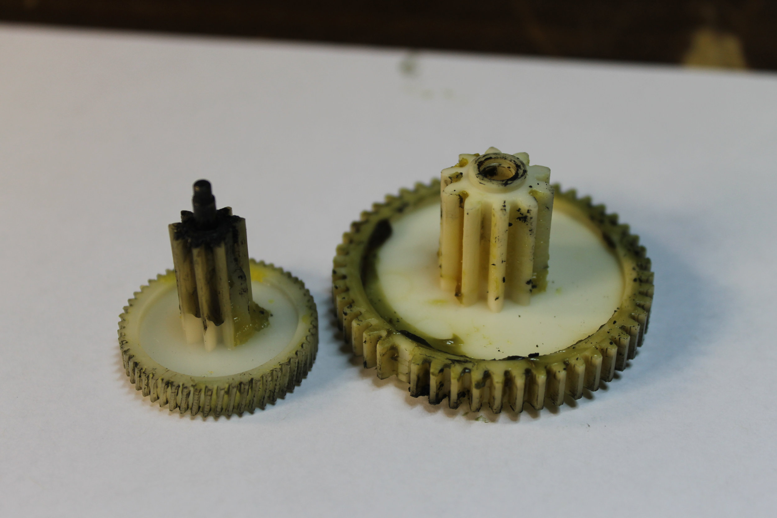
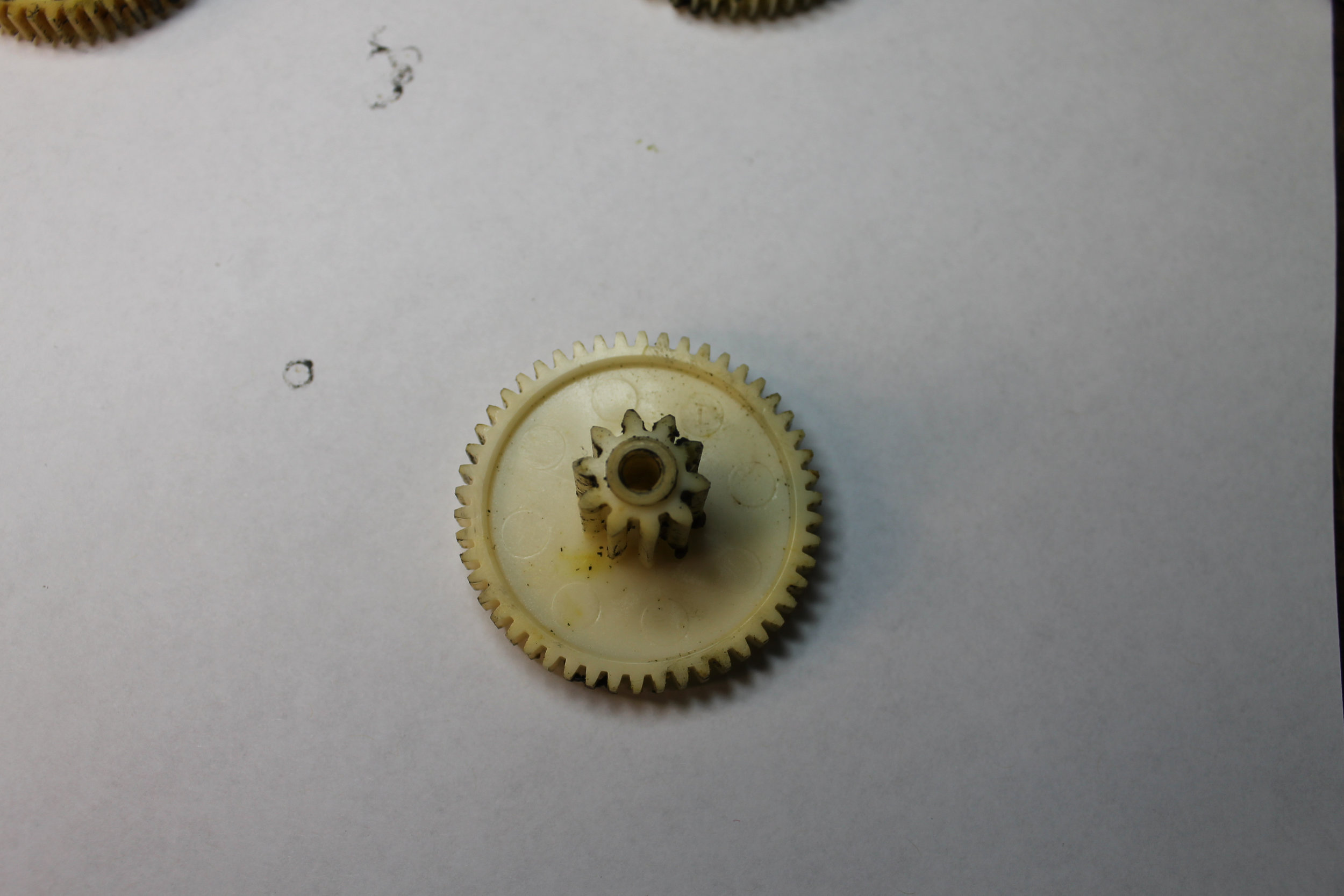
3 Gears
Resistance Measurements
The first thing we should to when evaluating the health of your cruise actuator is to perform a series of resistance checks. These checks will tell us the health of items 1-3 above. Items 4 will be checked when you perform the current draw test below.
I’ve listed the tests in the below image and I’ve included the values from my actuator that I use for bench testing.

Note: In the chart below, ground refers to pin 1 on the actuator as it is the ground for the actuator.
Motor / Solenoid Current Draw
Next we want to check the current draw on that DC motor. As too much current can damage the amplifier. You want to monitor current when pins 4 and 5 are connected to power. Ideally you should see between 120-180mA or .12-.18 Amps.
I have seen units with .2-.22 that still function normally. If you're up near 250mA or .25 I'd say it's time to consider changing up the actuator or sending the unit in to me for service. Sometimes the units are repairable sometimes not.
When you test current you want to place your multimeter in series with the object in test. That means to put the meter in the path of current flow. This differs from when you check voltages. When you check voltage you put the meter in parallel with the object in test.

You'll need access to a power supply of 12-13.5V. Some spare wire and you car's battery will do. I use an old computer power supply.
You'll need a meter that will measure DC current. Most cheap meters will do this. For this demonstration I'll use a cheap Cen-Tech meter I bought on Amazon. Here's the one I've got, also available from Harbor Freight Cenn-Tech 90899 I also have a more expensive Triplett 9045 unit.
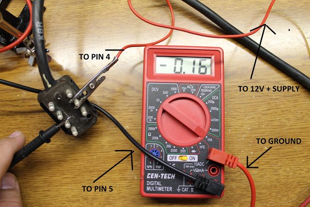
Next you'll want to configure the meter properly. Most meters will have a 10A position somewhere on it. This means it can handle up to 10 Amps of current. You'll want to use this as most of these meters are fused to a low current. This also will avoid confusion trying to interpret the results on the display. The display will show in amps. In addition to setting the dial to 10A you'll need to put the red lead in the 10A position. See photo below.
You'll want to wire a solid connection from either side of the battery or power supply. For this demonstration I chose to connect the 12V supply to the actuator's pin 4.
Next you'll place the meter in the path of the other wire as shown in the picture above.
Turn on your power supply or tap the lead to pin 5. You should hear the motor whur and a reading should appear.
Now we want to ensure the solenoid is functioning, to do this simply ground pin 6 and tap 12V to pin 7. You should hear a loud click. Only tap for a brief second.
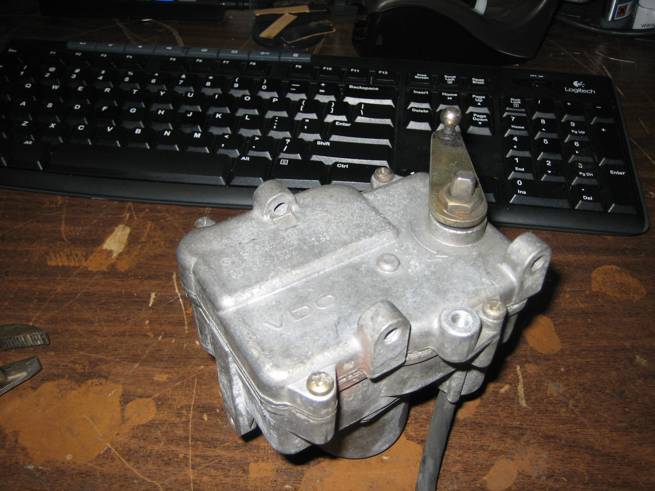
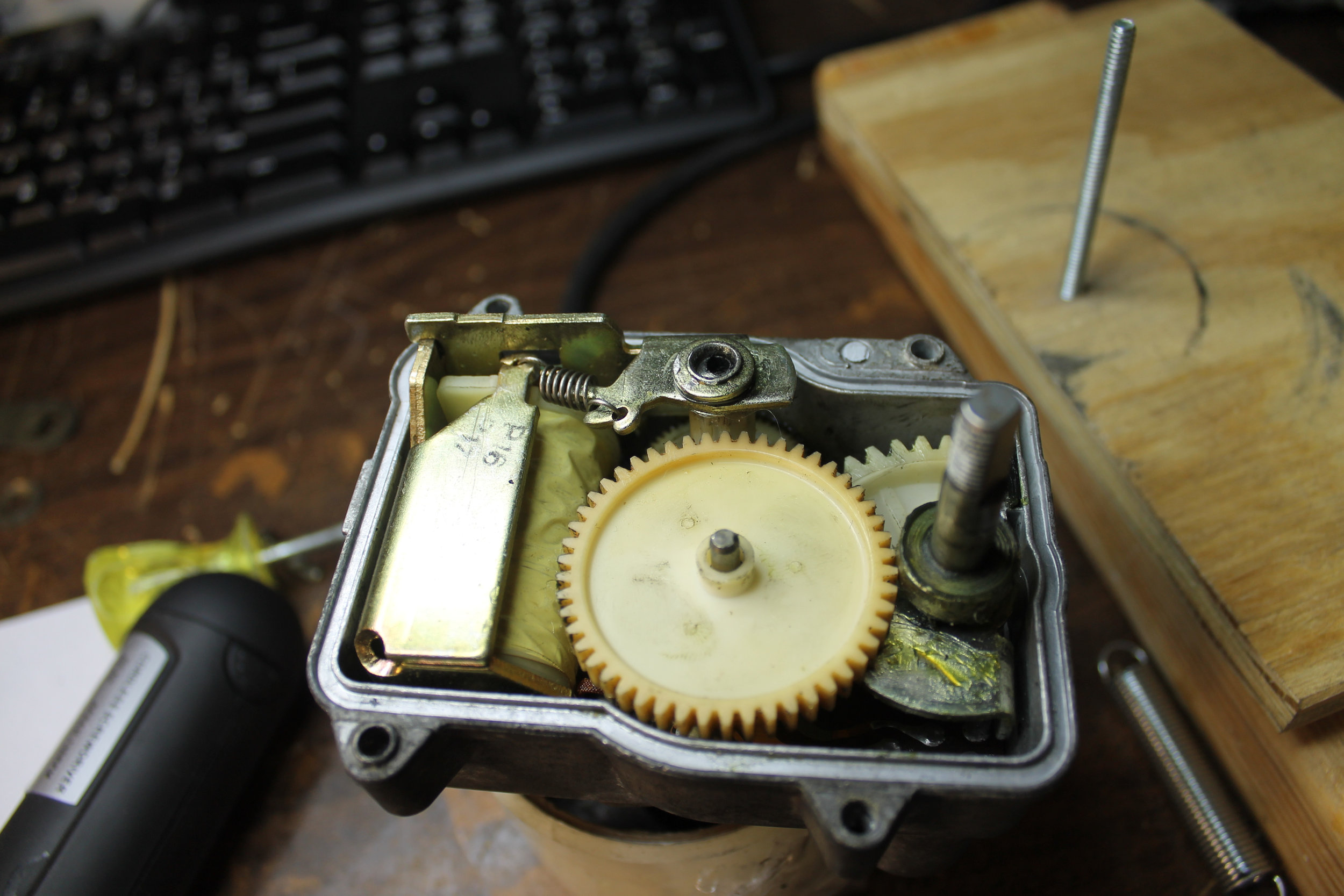
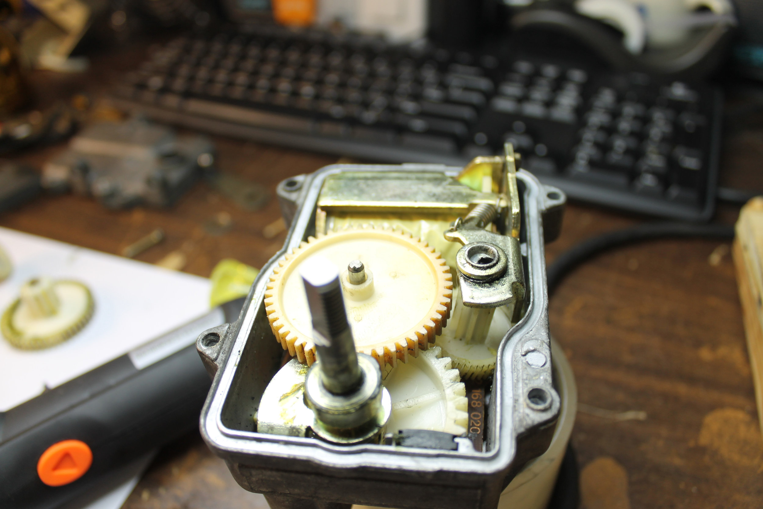
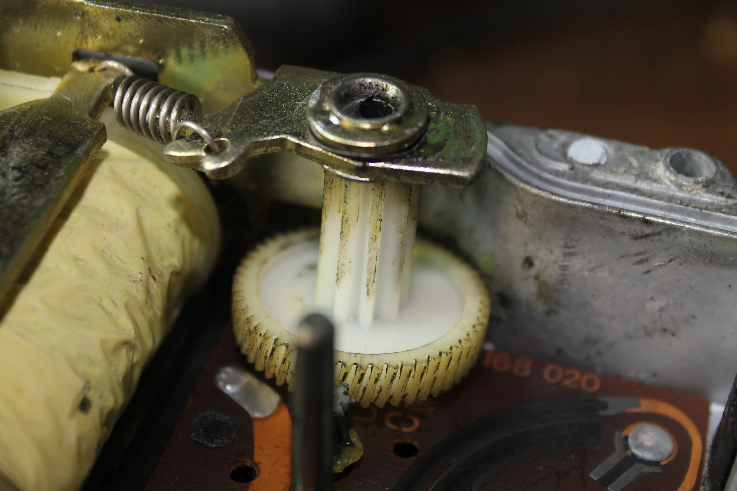
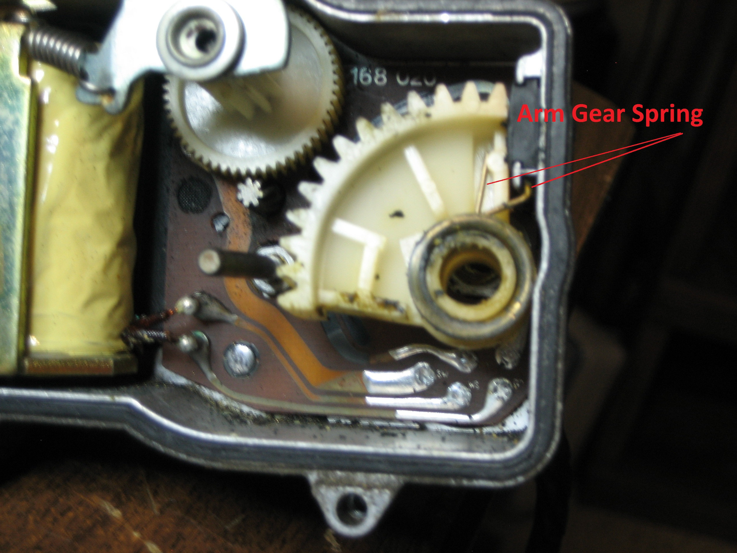
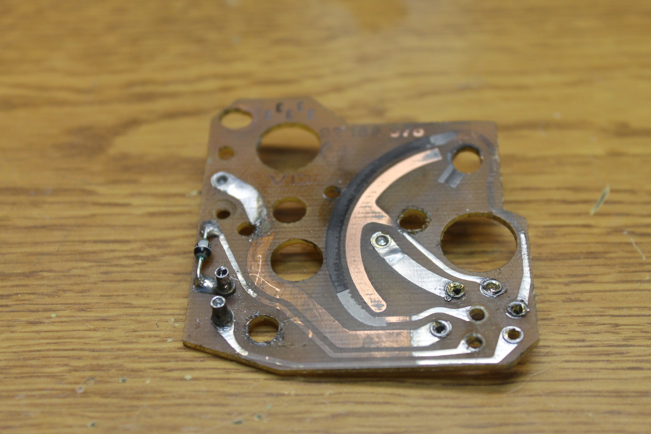
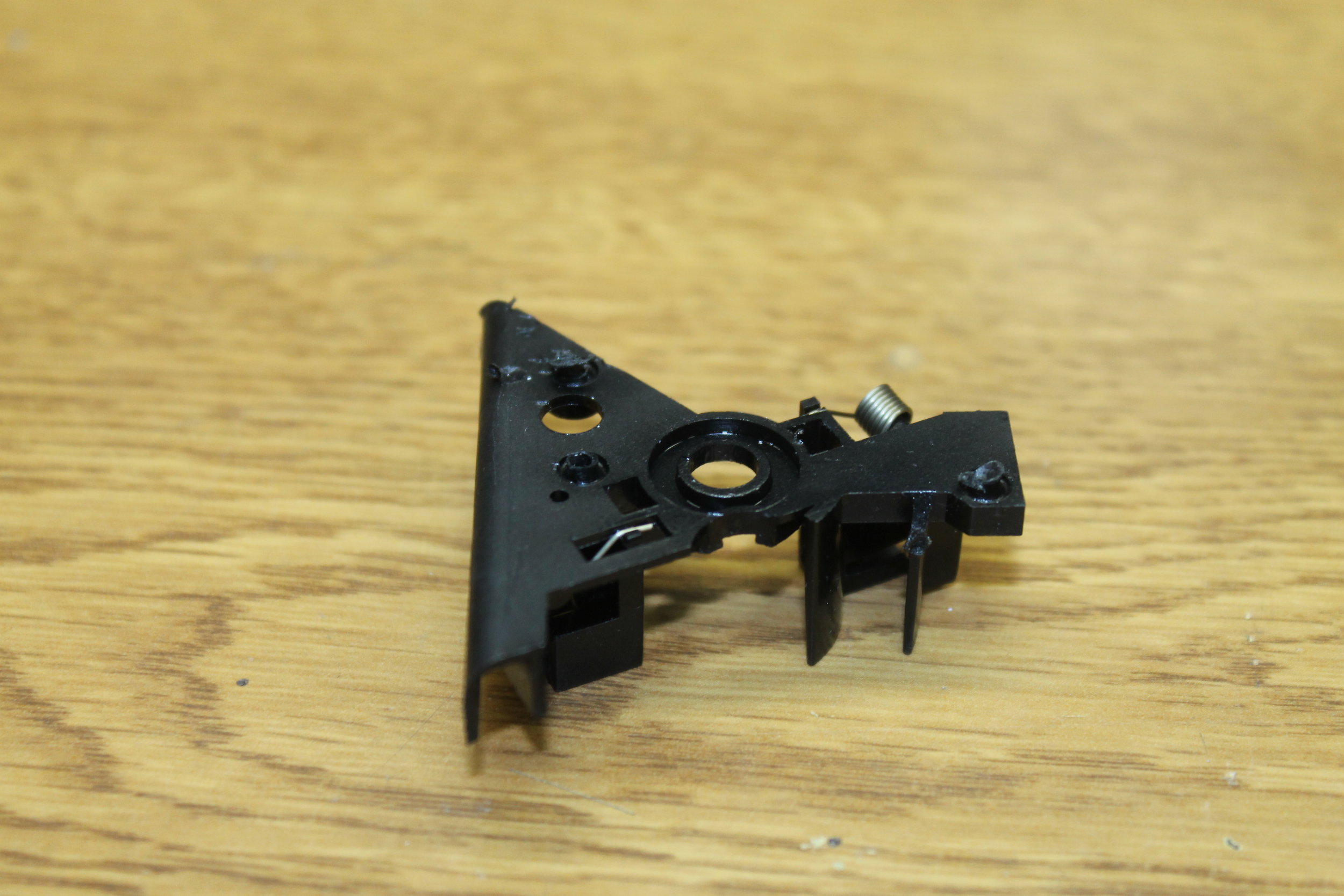
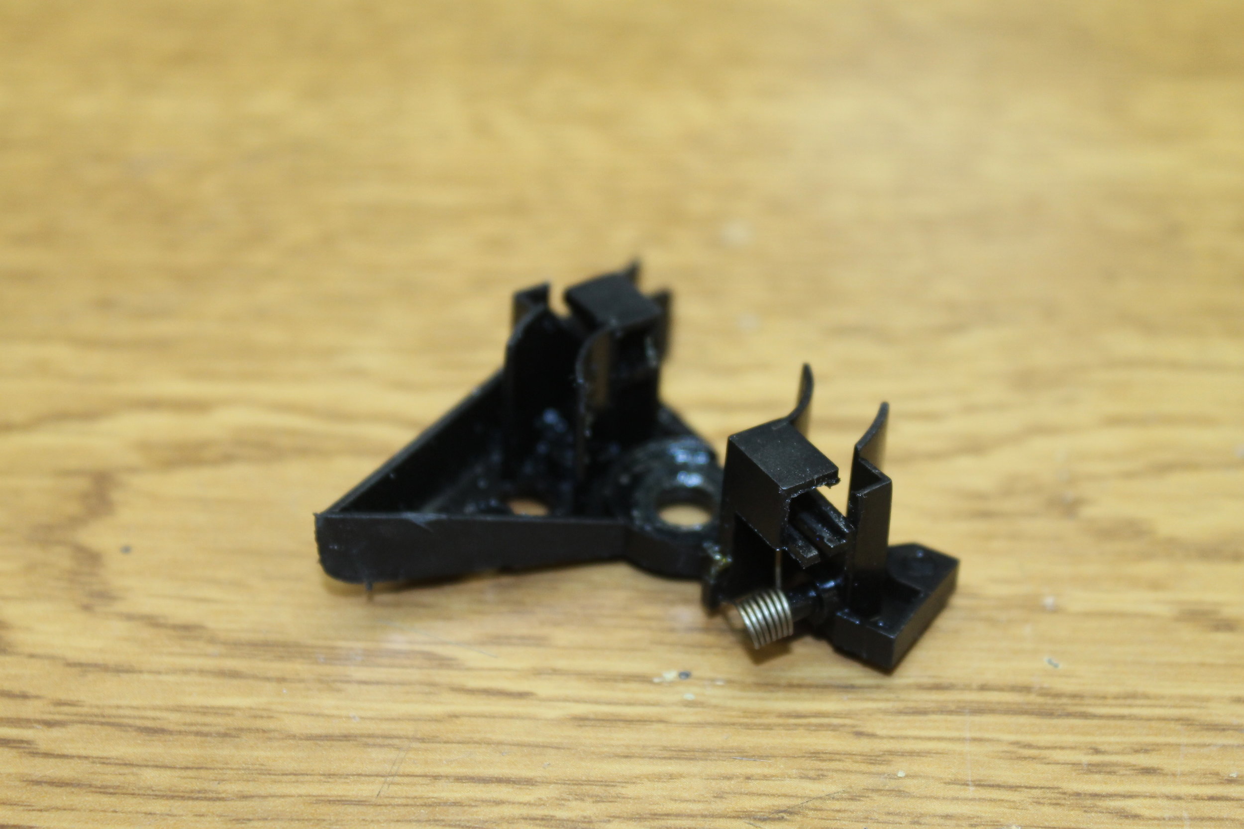
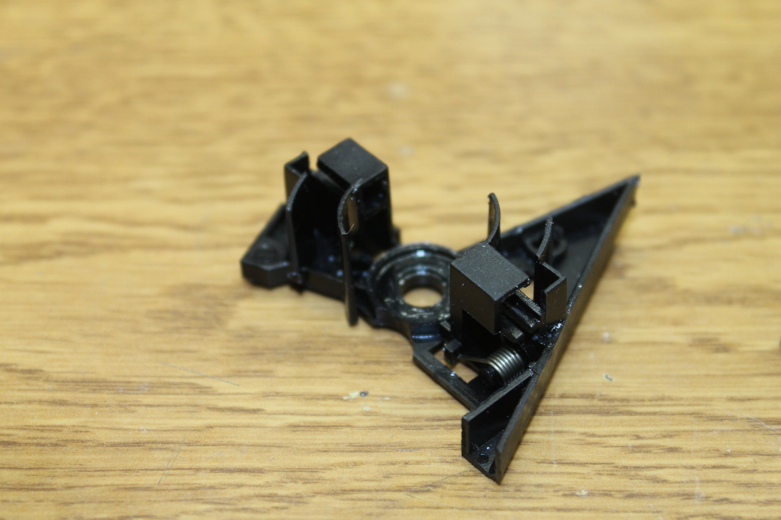
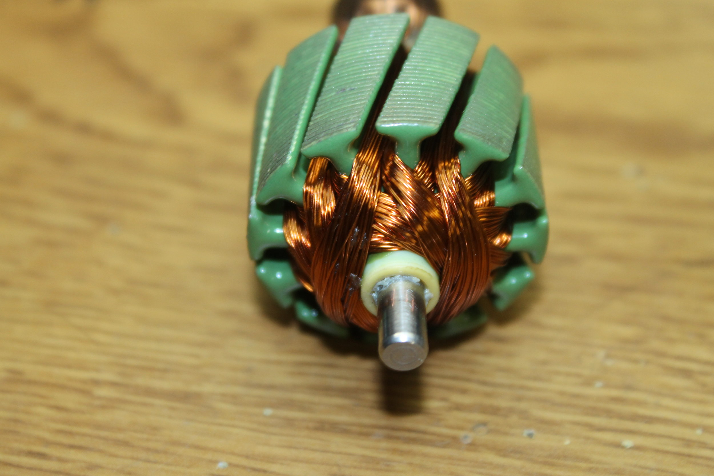
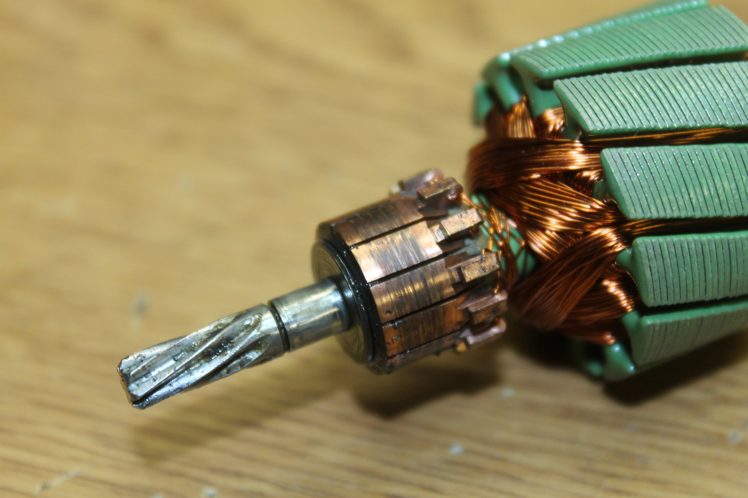
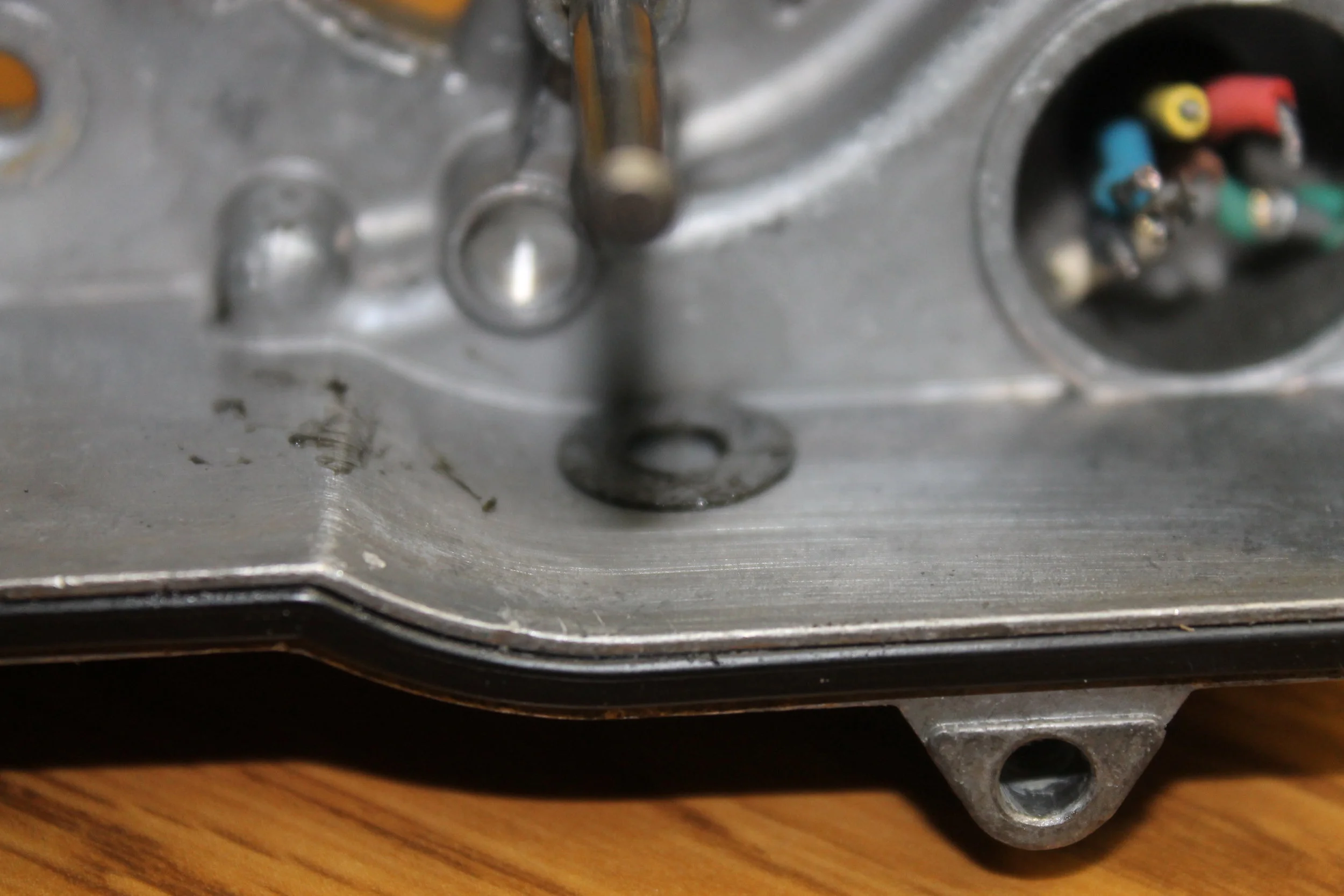
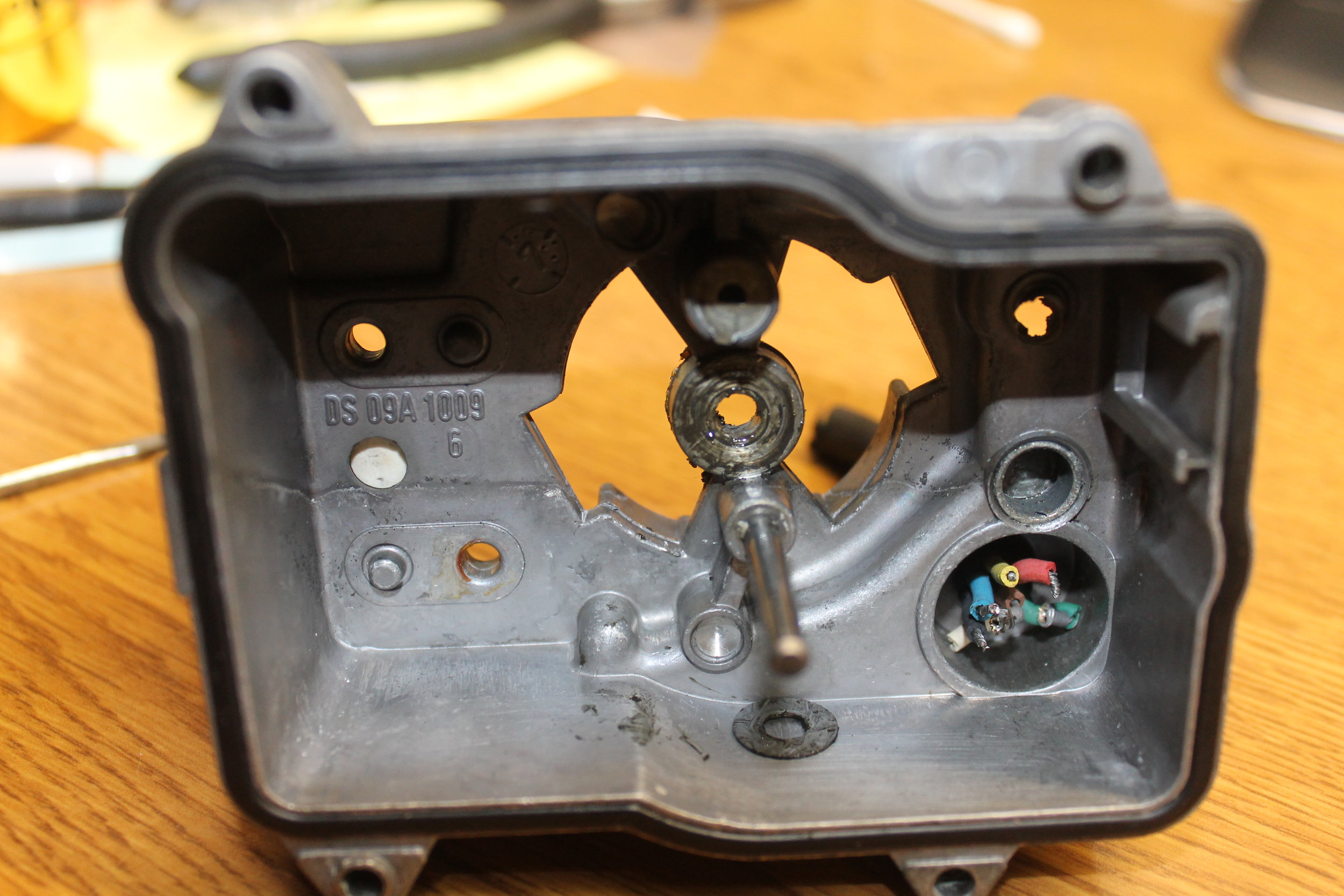
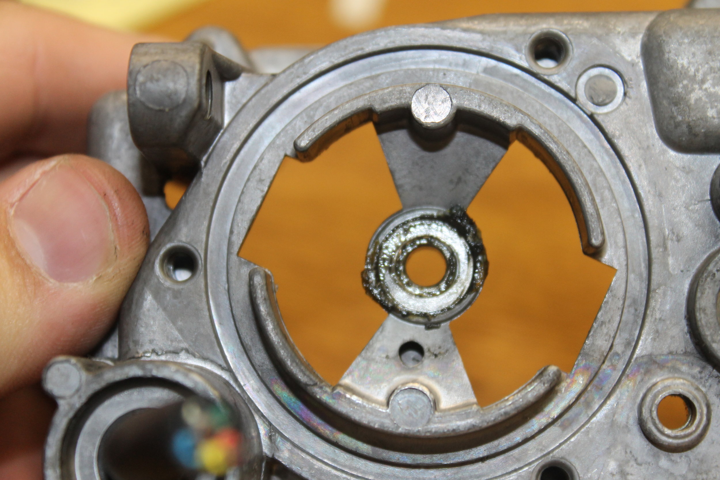
Inside the box: Cruise Control Actuator